Assignment 4: Designing a Box with Interference Fit
Assignment Details
Design a box that is made up of flat panels with fingerjoints/boxjoints, tabs, or another joining method design for sheet material. Your panels and all tabs need to be 3d printed, but you cannot 3D print the box in one piece. Design for an interference fit, that is, when you press the panels together they should join tightly and not need additional fasteners and screws.
Furthermore, they should provide a close enough fit that your resulting box can hold something like sugar without leaking.
Phase 1: Ideation & Sketching
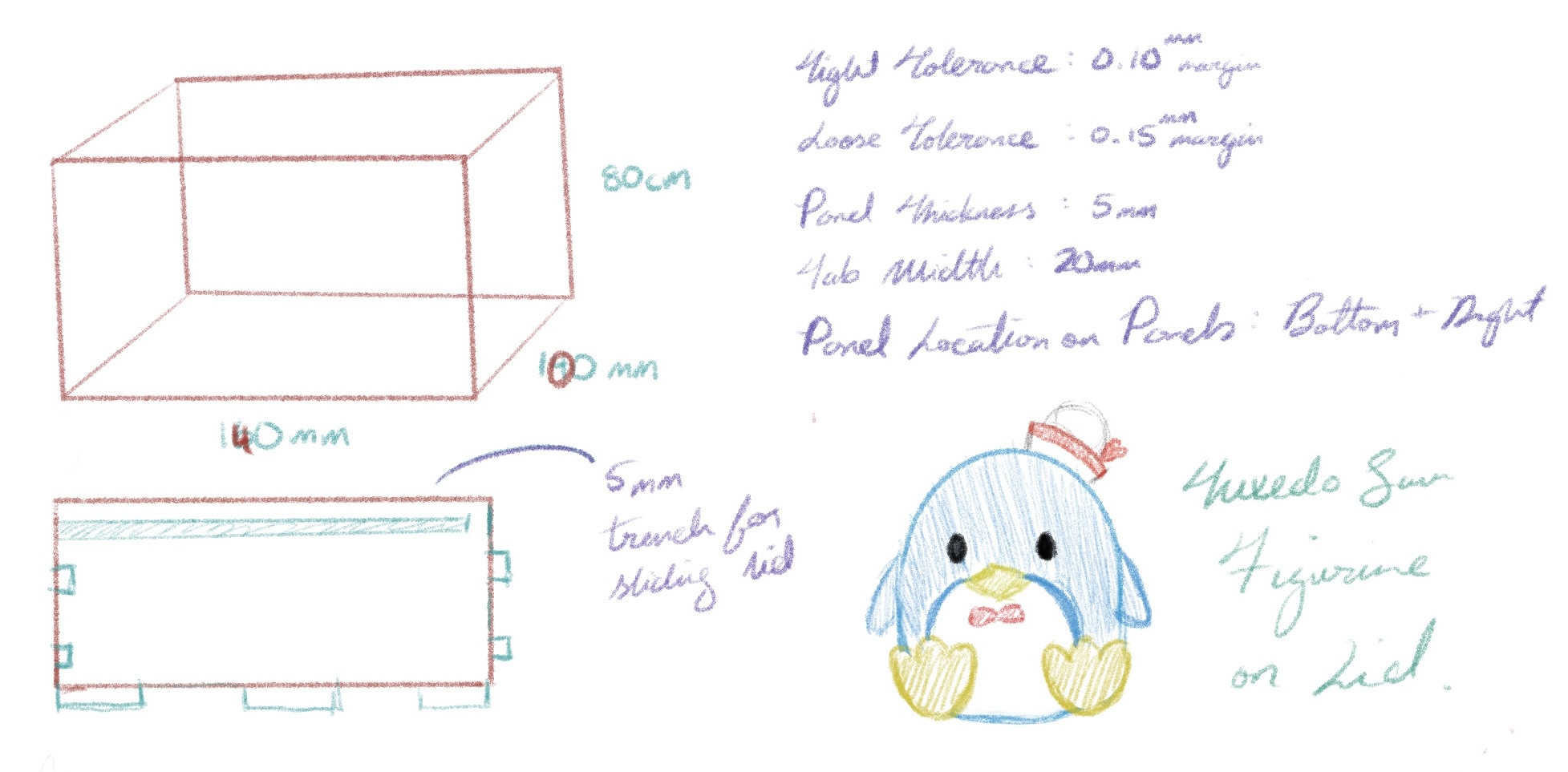
Having done something similar for Assignment 2, I wanted to challenge myself and attempt to try different techniques with 3D printing.
As usual, I start all of projects with a general sketch with notes on how I envision the final product. From Assignment 2, I learned that it's best if you design the box sides first, then the bottom/top. This is mainly because when you design the tabs, you also have to account for material thickness and fit tolerance. So I aimed for my tabs to be about 20mm, but I also needed to find out my fit tolerance to design the fitting of the tabs.
Phase 2: Tolerance Test
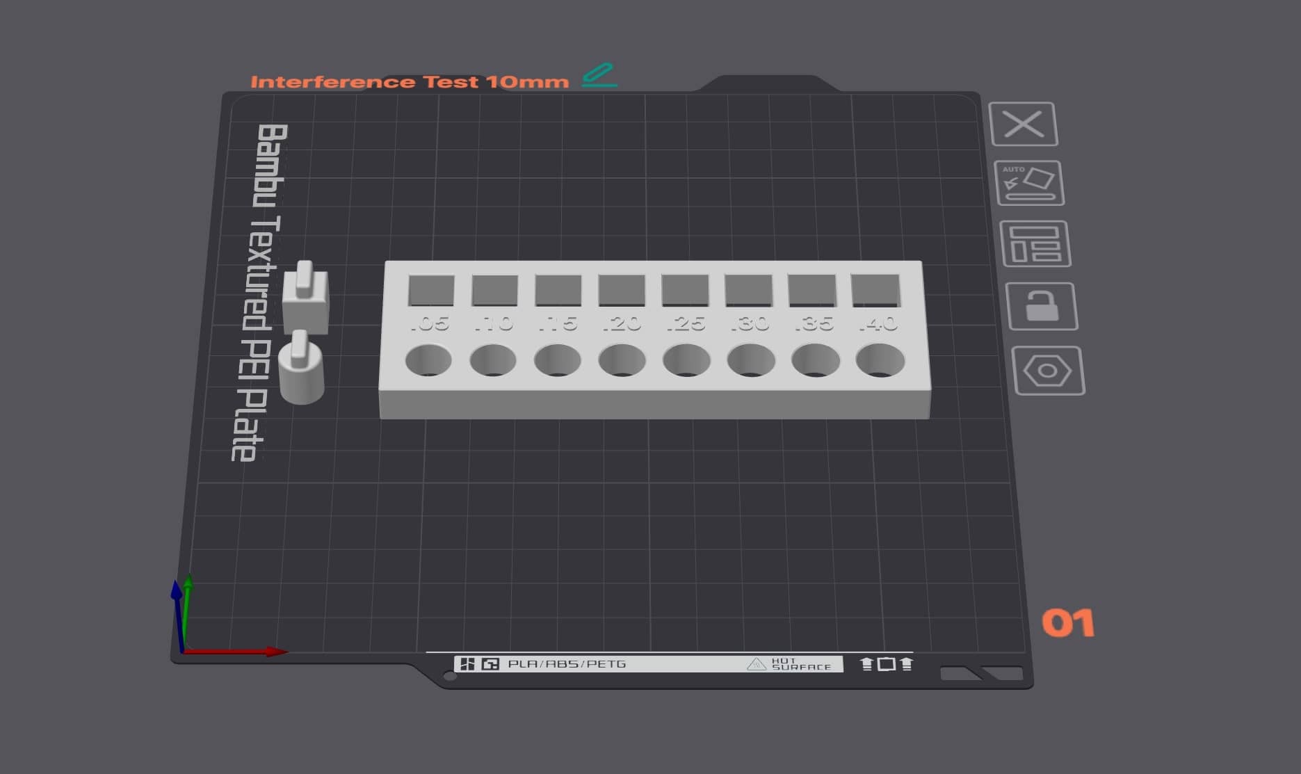
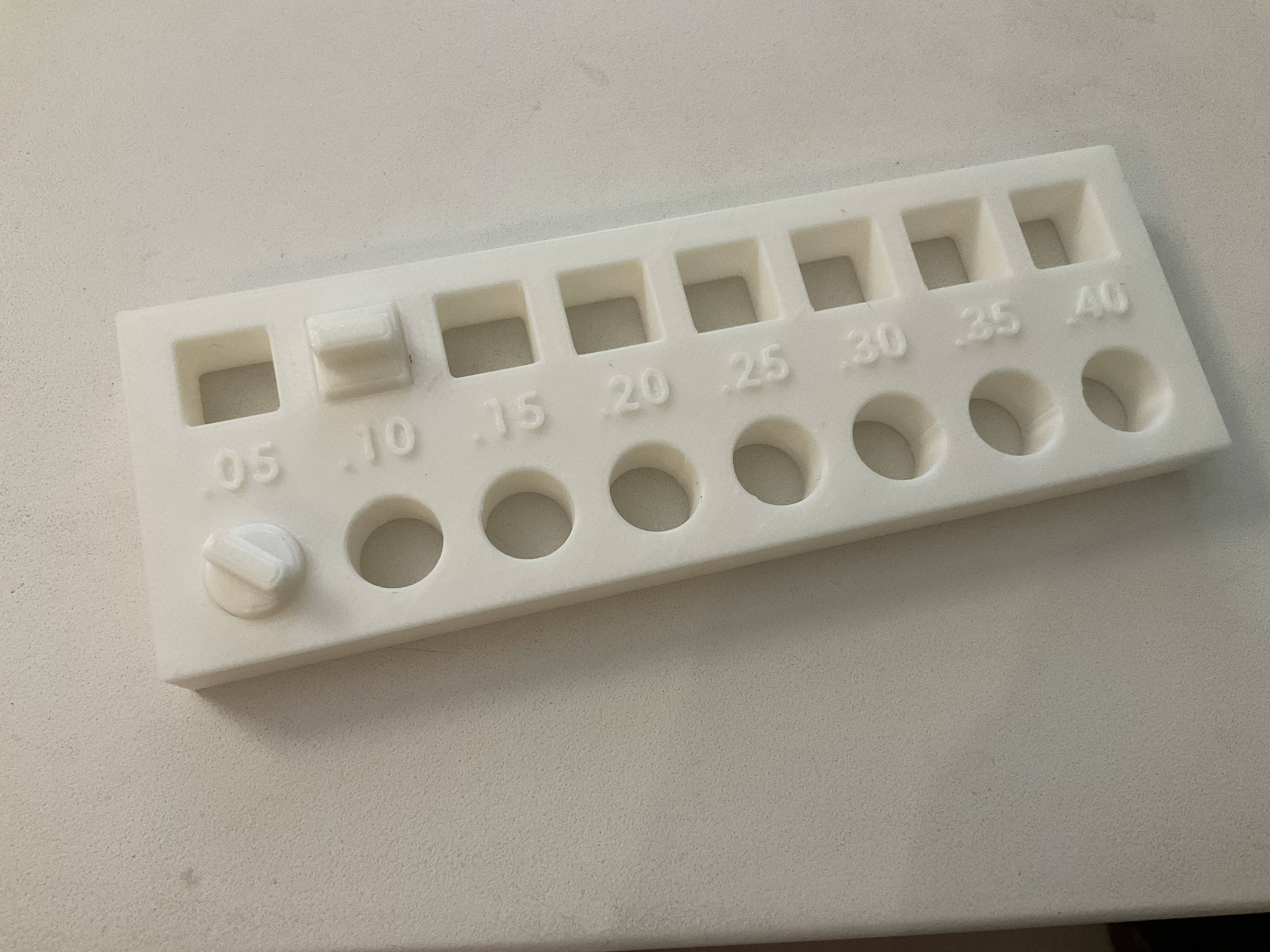
I decided to design and print out a tolerance test first. I planned on making my panel thickness 10mm (I learned that the thinner the material, the less tolerance there is), and designed a simple test by increasing the gap by 0.05mm. I also planned on making a sliding top, so I knew I needed a larger gap for lid.
From my tolerance test, I found that a tight fit for my panels would be 0.05mm - 0.10mm tolerance. A looser, but snug fit for my sliding lid would be 0.10mm - 0.15mm. I was also aware that my machine tends to print with a -0.20mm error rate, which I needed to account for in my design.
I also made a note of the settings I used to print my tolerance test, as I would need to use the same settings to achieve the most similar results. I used the 0.20mm standard settings for my machine in Orca, but slowed down the inner wall speed to 100mm/s and outer wall speed to 150mm/s, in order for a more accurate outline for my tabs and gaps.
Phase 3: Model Creation
As I mentioned earlier, I started by modelling the side panels and making the sides fit into one another first before working on the bottom panels. I must admit, I did cheat a little bit and used Autodesk Fusion 360 instead of Rhino, just to try a different program and see if I liked it better *spoiler* I think Fusion 360 is superior (˵ ¬ᴗ¬˵)
When modelling, I wrote down the sizes of my tabs and gaps (which is SO much easier to figure out in Fusion 360), so I could use/adjust them later for the lid and bottom panel.
I decided to print out one of each short panel and long panel to see if those pieces fit before moving on and designing the bottom panel and finally the lid. This way, I can also use my calipers to confirm the error rate of my tolerance tabs to make a better fit.
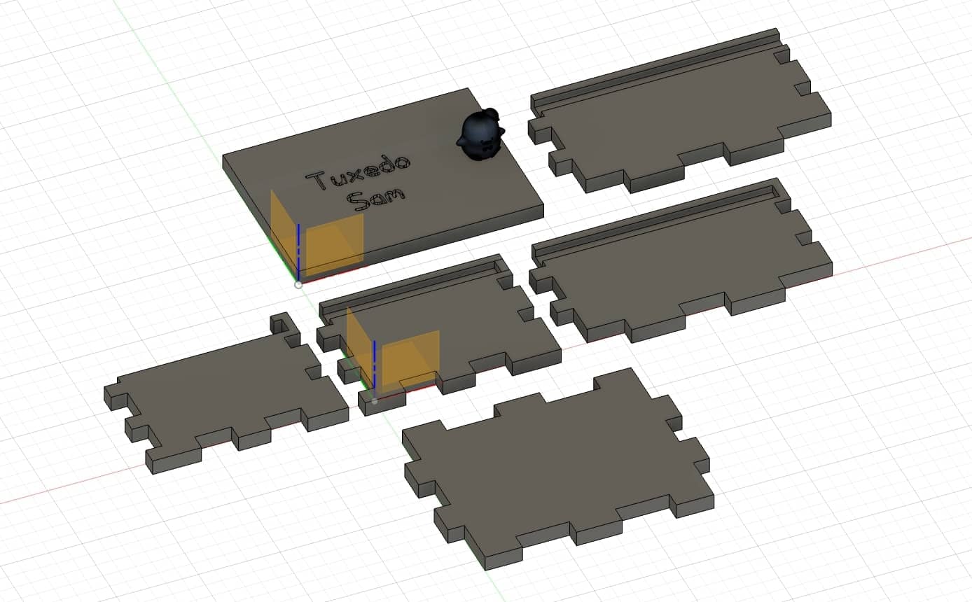
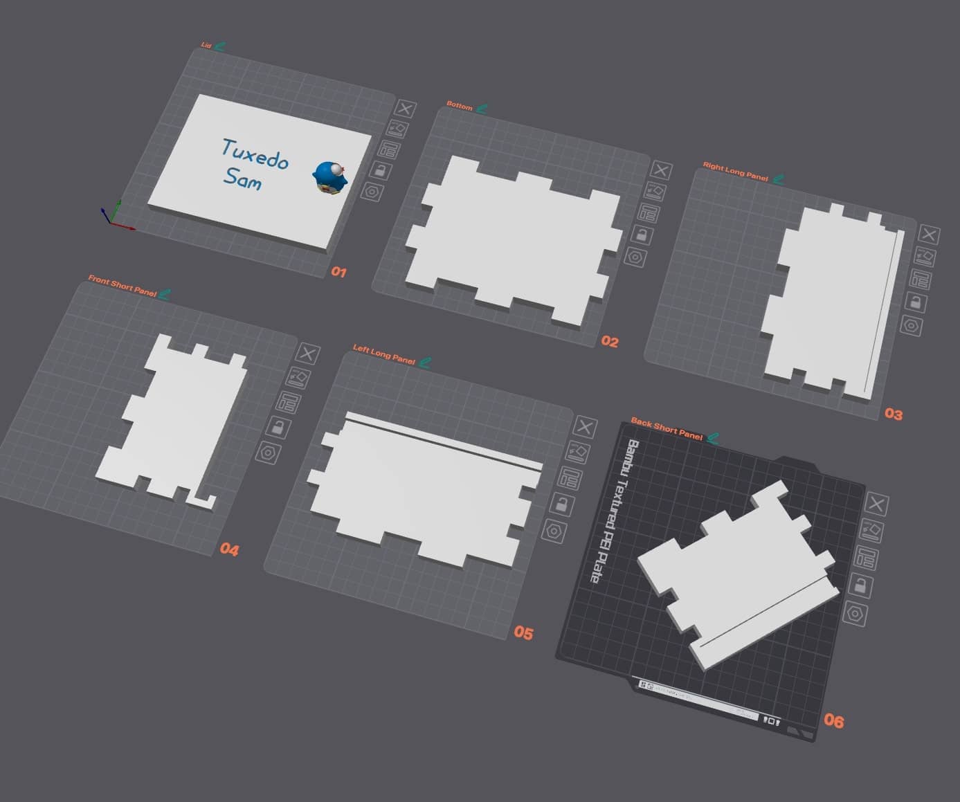
I ended up not having to make any test pieces/prototypes by using this method which saved me time and filament! For the side panels and bottom panel, they each took roughly 45 - 60 min to print.
The longest print was the lid, where I wanted to experiment with a text engraving and a figurine that would act as a knob to slide the lid on and off. This print took 8 hours and 30 min mainly because of the filament color changes for the engraving and figurine. I decided to use a lightning infill at 10% to help reduce print time by about 30 min.
Phase 4: Sugar Test
After making all of my pieces, it was time for the sugar test. I contemplated using brown sugar instead of white sugar, because the sugar particles are larger (ʃƪ¬‿¬)
To be fair however, I decided to buy a bag of white sugar for this and conduct the test with white sugar. From the video, you can see that there was no leaking apart from a few specks (although that may have been from my sugar pour mishap a few moments earlier).
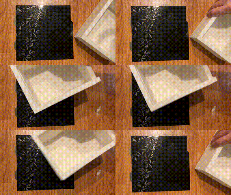
However, I noticed that because I treated this box horribly since its creation (dropping it a few times, taking the pieces apart and putting them back together, etc.), the pieces don't fit as good as they used to and I have been noticing larger gaps in the bottom.
Phase 5: Reflection
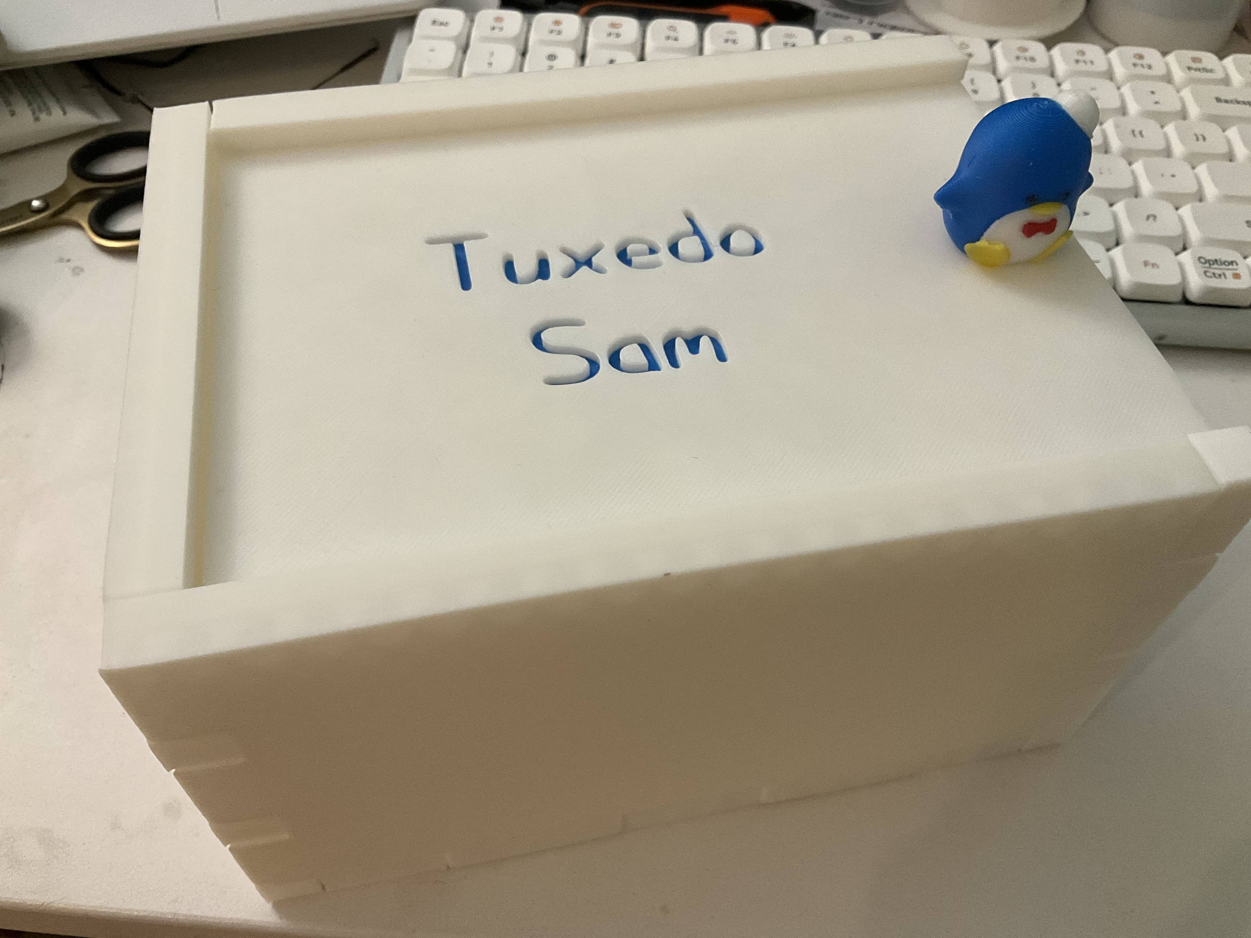
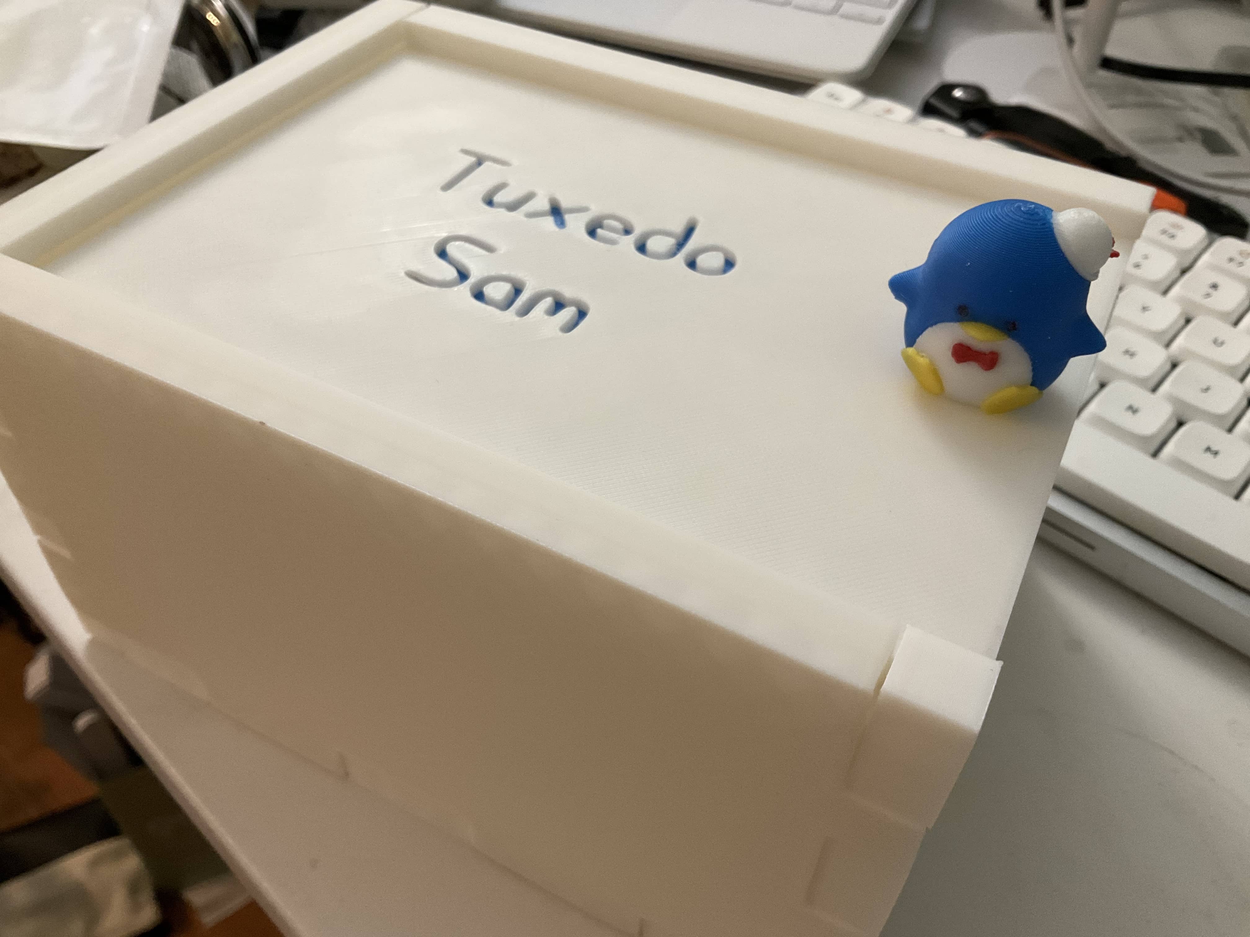
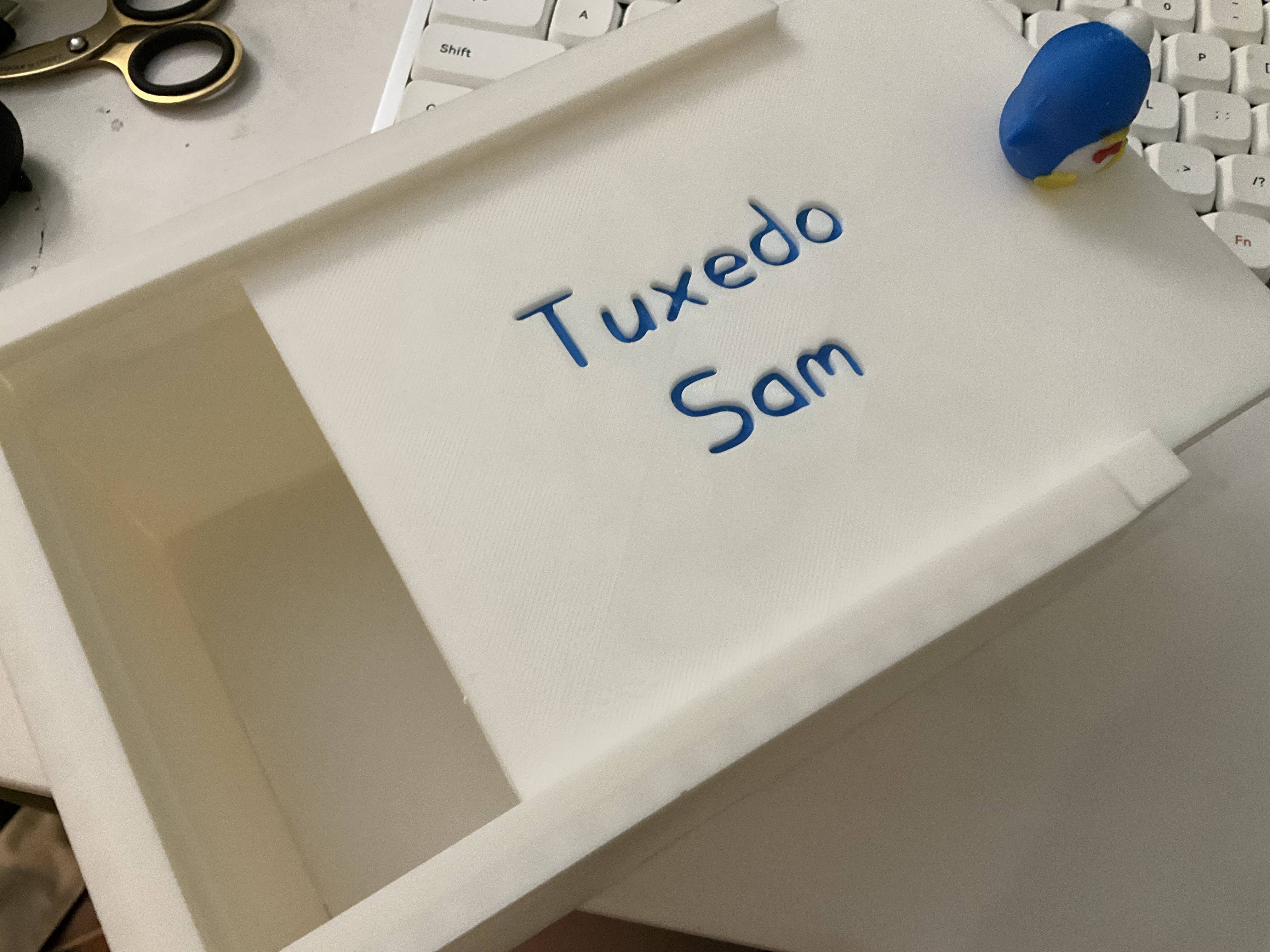
Overall, this project taught me the significance of making pieces as you go in order to save your materials and affirm your measurements (since there are margins of error with 3D printing -- especially at higher speeds).
I also learned that PLA is not indestructible and can certainly warp from abuse. I don't think my box can pass the white sugar test anymore after I abused it, but I did test it when brown sugar and it still passed that one!